
Have you ever wondered why there are so many different types of devices in a network, like switches, routers, or network cards?
Or have you ever come across a situation where you had to set up an IP address, or heard about a MAC address for the first time, and wondered why there are so many different types of identifiers?
By the end of this post, you’ll understand what the network stack really is, the roles each of these devices play, and—most importantly—why they matter. I also believe this post will help you see the bigger picture of networking by connecting all the dots.
The 5 Layers (TCP/IP Model)
I believe the best way to break this down is by looking at it from a practical point of view. So, let’s start here: we’re all familiar with applications. In fact, you’re reading this blog using a web browser—just another type of computer application.
In TCP/IP Model, there are 5 layers, and the top most layer corresponds to the application layer. Let’s start from application layer, and see how it would propagate to a another application in a different computer (device).
Application Layer (Layer 5 of TCP/IP Model, and 7 of OSI)
The main purpose of a network stack is to enable communication between applications. That’s why the topmost layer in the stack is the Application Layer.
At this level, the message format can vary widely depending on the application. There’s no single standard for how data should look, because each application generates its own raw data based on its purpose.
However, when an application uses a specific protocol—like HTTP for web pages or SMTP for emails—the data must follow the rules defined by that protocol. These protocols provide a standard structure for how messages should be formatted and understood.
Transport Layer (Layer 4 of TCP/IP Model, and OSI)
Even though the Application Layer can generate messages in any format and length based on the protocol it uses, the underlying stack must ensure that these messages are reliably delivered to the recipient. This is where the Transport Layer comes in. It takes the message from the Application Layer and, if necessary, splits it into smaller chunks for efficient transmission.
This layer also uses different protocols depending on the requirements—like TCP for reliable delivery or UDP for faster, connectionless communication. Additionally, to make sure the message reaches the correct application on the destination device, the Transport Layer uses port numbers. Each message includes a source port and a destination port to uniquely identify the sender and receiver applications.
At this stage, the payload is simply the original message passed down from the Application Layer.
Network Layer (Layer 3 of TCP/IP Model, and OSI)
So far, we’ve seen how the source and destination applications can be uniquely identified using port numbers from the Transport Layer. Now, we need a way to uniquely identify the devices (or hosts) on which these applications are running. This is where IP addresses come into play.
An IP address uniquely identifies a device in a network. At this layer—the Network Layer—the data unit is called a packet. The key pieces of information added to each packet are the source and destination IP addresses. These addresses remain unchanged as the packet travels across networks.
The payload at this layer is the segment received from the Transport Layer (either TCP or UDP). The protocol used here is the Internet Protocol (IP), which exists in two major versions: IPv4 and IPv6.
If the sender doesn’t know the destination IP address but does know the domain name (like example.com), the system first checks the local DNS cache. If the address isn’t found there, a DNS query is sent to known DNS servers to resolve the domain name to an IP address.
Data Link Layer (Layer 2 of TCP/IP Model, and OSI)
Now that we know the destination IP address, the next step is determining the immediate destination port within the local network to correctly propagate the data frame. For devices to communicate within a local network, they need to know each other’s MAC addresses.
Every device on a network has a unique Data Link Layer address called a MAC address (Media Access Control). This is a 48-bit hexadecimal number that ensures each device can be individually identified.
But how does a device figure out the MAC address associated with a given destination IP address? This is where ARP (Address Resolution Protocol) comes in. ARP allows a device to query the local network to map the IP address to the corresponding MAC address, enabling correct delivery of the data frame.
- First, the source device checks its ARP table to see if there is already an entry for the target IP address. If it finds an entry, it retrieves the corresponding MAC address from the cache.
- If not, the source device generates an ARP request message. It fills in its own MAC address as the sender’s hardware address, its own IP address as the sender’s protocol address, and the target IP address in the destination protocol address field. The target hardware address (MAC) will remain blank, as the source device is trying to discover it. The source device then broadcasts the ARP request message to the local network.
- Since this is a broadcast, every device on the local network receives the ARP request. Each device compares the destination protocol address (the target IP address) against its own IP address. If it doesn’t match, the device simply discards the packet without taking any further action.
- If there’s a match, the destination device generates an ARP reply message. It fills in its own MAC address as the sender hardware address and uses the sender’s details (from the ARP request) to populate the relevant fields. The destination device also updates its ARP cache with the sender’s information. The reply is sent as a unicast message directly to the source device.
- Finally, the source device receives the ARP reply, updates its ARP table with the target device’s MAC address, and is now ready to send data to the destination device using the correct MAC address.
Now that we have all the required information, let’s clarify one more important point. When the source device is communicating with another device on the same IP network, the target for the ARP request is the destination device’s IP address. The source device will use ARP to resolve the destination device’s MAC address within the local network.
However, if the source device is trying to communicate with a device on a different IP network, the target for the ARP request will be the Default Gateway’s IP address. The Default Gateway is the router that connects the source device’s local network to other networks. The source device will send an ARP request to resolve the Default Gateway’s MAC address, allowing it to forward the packet to the correct destination across the network.
Physical Layer (Layer 1 of the TCP/IP Model, and OSI)
At this point, we have a data frame that’s ready to be sent to the destination device. But how do we actually transmit this abstract representation of data? As you may already know, information is sent using various types of signals. These signals can be electrical signals through copper wires, optical signals through fiber optic cables, or electromagnetic waves through Wi-Fi and other wireless technologies.
So, now it’s clear that we need to transform the data frame into a relevant signal that can be transmitted over the appropriate medium. This is exactly what the Physical Layer does. It takes the data frame from the Data Link Layer and converts it into a signal that can travel across the medium, whether it’s through wires, fiber optics, or wirelessly, to reach the destination.
| TCP/IP Model | OSI Model |
| Application Layer (5) | Application Layer (7) |
| Session Layer (6) | |
| Presentation Layer (5) | |
| Transport Layer (4) | Transport Layer (4) |
| Network Layer (3) | Network Layer (3) |
| Link Layer (2) | Link Layer (2) |
| Physical Layer (1) | Physical Layer (1) |
What happens at the receiver end?
At the receiver’s end, once a signal is picked up by a device on the network, how it responds depends on the type of device. Let’s assume for simplicity that we’re using Ethernet for the local network.
1. If the device is a Physical Layer device, like a network hub, it can only understand signals and doesn’t have the capability to interpret the content. Since it operates at the Physical Layer, it cannot make any decisions based on higher-layer data. As a result, the hub simply broadcasts the signal it receives from one port to all other ports, forwarding it to every device on the network.
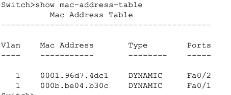
2. If the device is a Link Layer device, like a network switch, it has the intelligence to understand and make decisions based on MAC (physical) addresses. When the signal is received, the switch decodes it and checks the destination MAC address against its MAC forwarding table (also called a bridging table). If a match is found, it forwards the data frame to the appropriate port that corresponds to the destination MAC address.
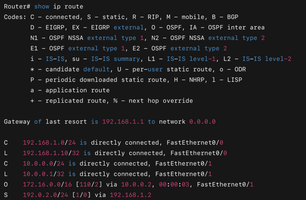
3. If the device is a Network Layer device, like a router, it can make decisions based on IP addresses. Routers also have a Link Layer component to forward frames based on MAC addresses, just like a switch. If the router can make a forwarding decision based on MAC addresses, it will forward the frame to the appropriate port. However, if the router needs to make a decision based on IP addresses, it moves the frame up to the Network Layer. Here, the router compares the destination IP address against its routing table to determine the best path for the packet.
If the destination IP is on a network directly connected to the router, the packet is forwarded to the corresponding interface.
If no exact match is found, the router will check for a default route. The default route points to the next hop on the network path.
If neither a match nor a default route exists, the packet will be dropped.
4. If the device is a computer (which has all layers), the process continues up to the Network Layer. When the packet reaches the Network Layer, the computer checks if the destination IP address matches its own. If it does, the payload is forwarded to the Transport Layer.
5. In the Transport Layer, depending on the protocol (TCP or UDP), sequencing and reassembly (if needed) occur to ensure that the data is complete. The message is then forwarded to the appropriate application based on the destination port number. Finally, the destination application’s layer receives the message and processes it, adhering to the protocol it uses.

I hope this has given you a clear understanding of the network stack, its purpose, and how the different layers interact to send a message from one application on your device to another application on a different device.
Thank you for following along!
Leave a Reply